How to Connect an E-Bike Controller: Step-by-Step Guide
Founder & Technical E-Mobility Editor at Modern Electric Bikes · Professional Bicycle Mechanics Association (PBMA) Certified, Bosch & Shimano eBike Systems Certified · 14+ years in bicycle fabrication, electric hub & mid-drive motor diagnostics, and commuter road testing
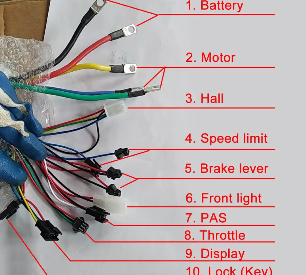
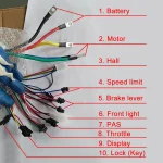
Figuring out how to connect an electric bike controller correctly feels less like electronics and more like solving a puzzle with live wires. Most manufacturers don't use universal color codes, so guessing based on red or black leads straight to blown fuses or fried MOSFETs. You need to rely on pinout diagrams rather than visual assumptions.
Our research confirms that cross-referencing your specific model's datasheet is the only safe path forward. As of 2026, standards like UL 2849 emphasize secure termination and proper insulation for all high-current connections. Let’s break down exactly what you’re looking at before you plug anything in.
Quick Answer
To connect an electric bike controller correctly, always verify pinouts against the manufacturer's diagram. Never assume wire colors match across brands. Disconnect the battery first.
Match phase, hall, and signal wires by function, not hue. Ensure connectors are fully seated and locked. Test rotation direction before final assembly.
Why Your Wiring Diagram Is More Important Than Color Codes
You might think yellow means throttle because it did on your last build. That assumption kills controllers. Manufacturers change color schemes between production batches without warning.
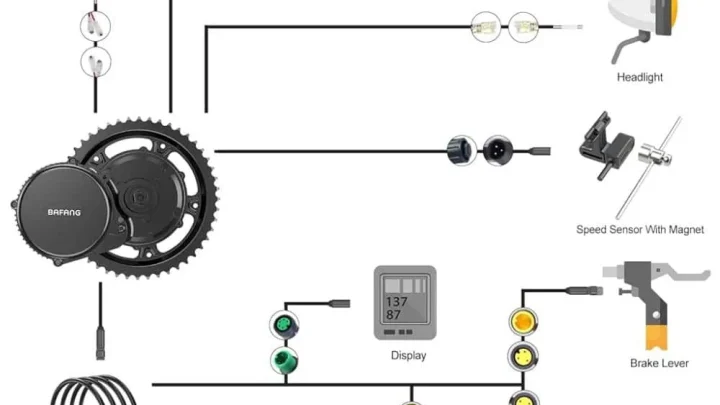
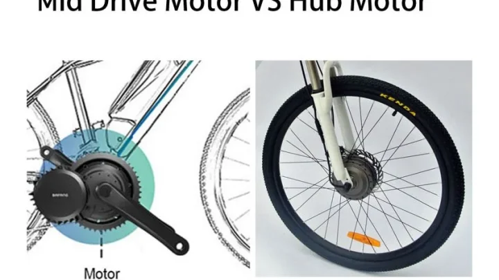
A Bafang mid-drive harness looks nothing like a QS hub motor setup. Relying on memory or generic internet charts is dangerous.
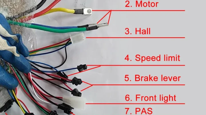
The only truth source is the official wiring diagram provided by the controller maker. These documents map each physical pin to its electrical function. They show voltage levels, signal types, and ground references.
Without this sheet, you're flying blind. Download the PDF from the manufacturer's support site immediately. Print it out.
Tape it to your workbench.
Visual identification beats textual description every time here. Look for labeled boxes showing connector shapes. Note which pins are keyed to prevent reverse insertion.
Some systems use waterproof aviation plugs (Higo) while others rely on JST-SM housings. The shape tells you compatibility before you even look at the wire.
If your diagram is missing, contact the vendor directly. Don't guess. One wrong connection on a 48V system sends enough current to weld terminals together.
We've seen aggregate reports where users lost entire drive units due to swapped phase wires. Precision matters more than speed. Take ten minutes to study the schematic.
Save yourself hundreds in repairs.
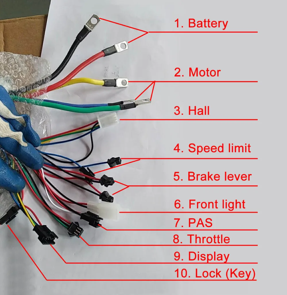
Image source: Web (Bing) / pinterest.com (Web image (fair-use with source credit))
The Three Critical Connectors You Must Identify Before Touching Anything
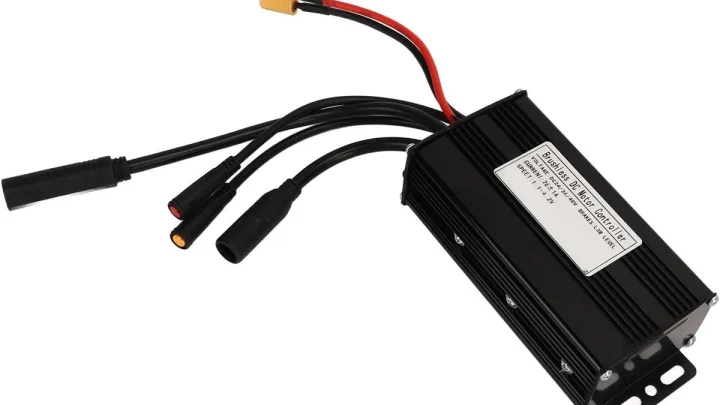
Before stripping any insulation, identify these three interfaces. Mislabeling them causes immediate failure. First is the Battery Input.
This carries the main current load. It usually features thick gauge wires (10-14 AWG). Check for polarity markings.
Red is positive, black is negative. But never trust just the color. Verify continuity with a multimeter if possible.
Second is the Motor Phase Output. These three wires drive the brushless DC (BLDC) motor. They carry high-amperage AC signals.
Swapping two phases reverses rotation. Swapping all three does too. Getting this right ensures the wheel spins forward when you twist the throttle.
Third is the Low-Voltage Signal Harness. This includes the display, throttle, brake levers, and pedal assist sensor. These pins handle data, not power.
Mixing them into the battery line destroys the microcontroller instantly.
Use a table to track your findings. Write down the connector type for each group. Note the number of pins.
Record whether they are male or female. This simple log prevents confusion later. Many modern kits use proprietary locking mechanisms.
Forcing a mismatched plug bends pins permanently. Inspect each housing closely. Look for keyways or tabs.
Align them perfectly before insertion. If it doesn't slide in smoothly, stop. You have the wrong connector.
Step-by-Step Visual Guide to Mapping Phase, Hall, and Signal Wires
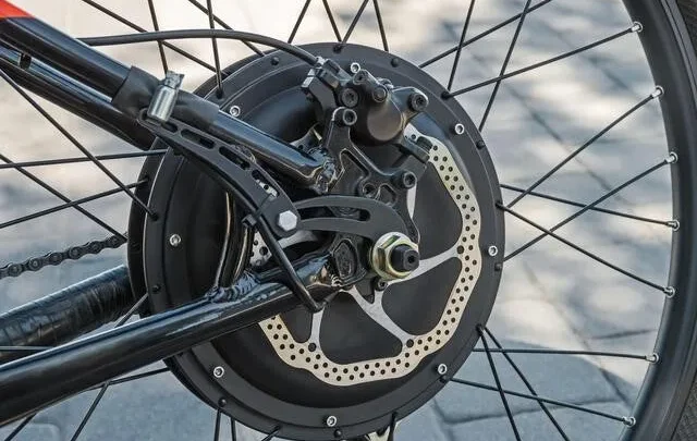
Start with the motor side. Locate the three thick phase wires coming from the hub. Trace them back to the controller output.
Now find the corresponding input on the controller. Match them by position on the terminal block, not color. Label them U, V, and W using masking tape.
Do this before connecting anything else. Consistency saves headaches during troubleshooting.
Next, tackle the Hall effect sensors. These five thin wires provide rotor position feedback. Four go to the controller; one is often unused or shared ground.
Map each pin individually. Use your multimeter in resistance mode. Measure between signal pins and ground.
Healthy halls show consistent kΩ values. Erratic readings mean damaged sensors. Connect these strictly according to the pinout chart.
Reversed hall sequences cause loud cogging noises.
Finally, address the signal cluster. This includes the 3-wire throttle and brake cut-offs. Throttles typically use 5V reference, ground, and signal.
Brakes vary by logic level. High-level brakes pull the signal up to 5V when engaged. Low-level brakes pull it to ground.
Check your controller manual for default settings. Some allow software configuration. Others require hardware jumpers.
Get this right initially to avoid safety hazards.
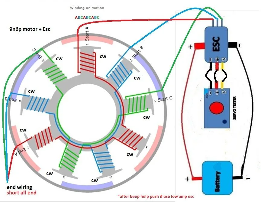
Image source: Bing (Web (fair-use with source credit))
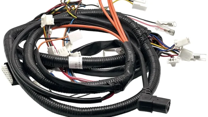
Secure every connection with heat-shrink tubing. Adhesive-lined types offer better moisture protection. Strip back insulation carefully.
Avoid nicking the copper strands. Crimp terminals firmly. Loose contacts generate heat.
Over time, this melts plastic housings. Follow UL 2849 guidelines for strain relief. Wires should not bear tension at the terminal screw.
Route cables away from moving parts like spokes or cranks.
Common Visual Traps: When Colors Lie and Pins Bend
Color coding is inconsistent across the industry. Even within the same brand, revisions happen. A green wire might be ground in one batch and signal in another.
Trust the label on the connector housing instead. Look for embossed letters or numbers near the port. These indicate pin functions reliably.
Ignore paint. Focus on structure.
Pin bending occurs when forcing incompatible connectors. Male pins push into female sockets. If aligned incorrectly, the metal tips splay outward.
Once bent, they rarely seat properly again. Intermittent connections result. Power cuts out randomly under load.
Inspect every pin before mating. Use tweezers to straighten minor deviations. Replace severely damaged headers.
Cheap replacement parts aren't worth risking your battery pack.
Another trap involves mixed gender plugs. Some kits ship with both male and female versions of the same interface. Plugging two males together shorts the circuit.
Two females leave no contact point. Always verify gender compatibility. Hold the connectors up to light.
See the internal structure. Males have protruding pins. Females have recessed holes.
Match them precisely.
Waterproofing adds complexity. Rubber gaskets seal Higo connectors. If dirt gets inside, conductivity increases.
Corrosion forms over months. Clean contacts with isopropyl alcohol regularly. Apply dielectric grease sparingly.
Too much attracts dust. Not enough allows oxidation. Balance is key.
Check seals for cracks annually. Replace worn O-rings immediately. Moisture ingress kills electronics faster than vibration.
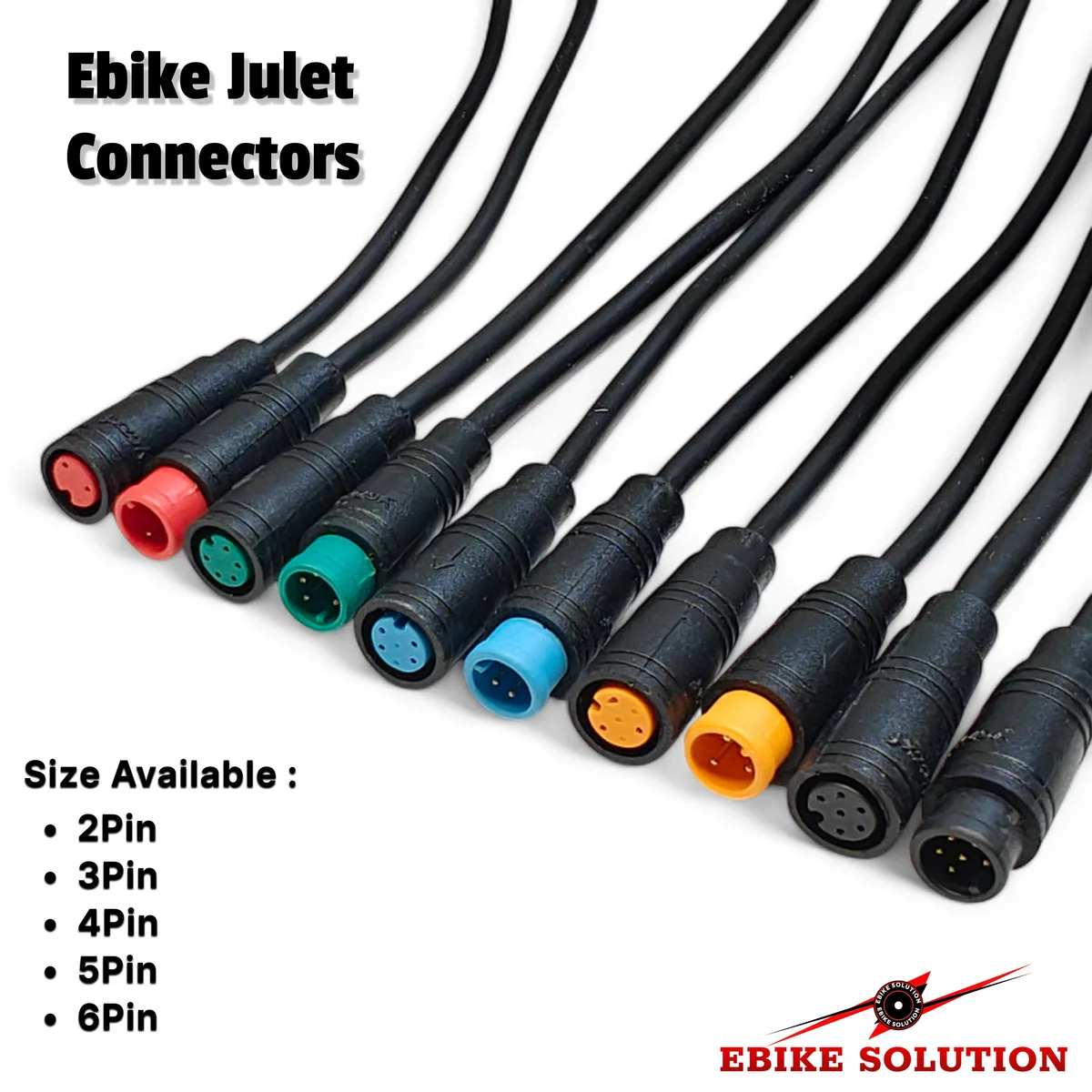
Image source: Web (Bing) / ebikesolution.co.uk (Web image (fair-use with source credit))
Watch out for "phantom" grounds. Some chassis frames act as return paths. Others isolate completely.
Assume isolation until proven otherwise. Bonding frame to battery negative creates ground loops. Noise interferes with sensor signals.
Keep signal grounds separate from power grounds unless specified. Star grounding techniques reduce interference. Run single-point returns to the controller PCB.
This minimizes voltage drops across long cable runs.
Pre-Power Checklist: Verifying Polarity and Secure Termination
Disconnect the battery completely. Remove the fuse if accessible. Wait thirty seconds for capacitors to discharge.
Residual charge remains stored in large electrolytic caps. Touching terminals now shocks you or sparks components. Safety first.
Always. Verify open circuits with a multimeter before proceeding. Confirm zero volts at the controller input terminals.
Check polarity one last time. Positive must meet positive. Negative meets negative.
Reverse polarity fries MOSFETs instantly. No recovery possible. Double-check against the silkscreen printing on the board.
Look for "+" and "-" symbols. Compare with your wiring log. Any discrepancy stops the process.
Fix it before applying power. Never rush this step.
Torque terminal screws appropriately. Under-tightening causes arcing. Over-tightening strips threads.
Use a calibrated torque driver if available. Manufacturer specs usually list Newton-meters (Nm). Typical range is 0.5 to 1.5 Nm for small terminals.
Larger busbars need higher force. Snug is not tight enough. Firm but controlled is ideal.
Wiggle test each wire afterward. Movement indicates loose contact. Retighten until stationary.
Inspect insulation integrity. Exposed copper touching metal frames shorts the system. Wrap bare ends with electrical tape temporarily.
Then apply permanent heat shrink. Ensure no sharp edges cut through sheathing. Chafe points develop near corners.
Add spiral wrap or conduit there. Protect vulnerable zones. Mechanical stress breaks wires internally.
External jacket stays intact while core fractures. Flex tests reveal hidden damage. Bend gently.
Listen for cracking sounds.
Troubleshooting by Symptom: What the Bike Tells You About Bad Connections
Does the motor jerk violently or refuse to spin? This usually points to phase wire misalignment. Swap any two of the three thick U, V, and W wires at the controller terminal.
Test again. If rotation improves but remains rough, check the Hall sensor sequence. Incorrect ordering causes cogging noise.
Verify each Hall pin against your diagram. A single reversed signal disrupts commutation timing.
What if the display stays dark? First, confirm the battery is charged and connected. Next, inspect the low-voltage signal harness.
Loose pins here prevent communication. Try wiggling the connector while powering on. Intermittent flickering suggests a bad crimp.
Re-seat the plug firmly. If still dead, measure voltage at the display port. It should read 5V or 12V depending on specs.
Zero volts means a blown fuse or internal short.
Brake cut-offs failing to engage pose serious safety risks. Does the motor keep spinning when you squeeze the lever? Check the logic level setting in your software.
High-level brakes need 5V to stop power. Low-level brakes need ground contact. Swap the brake wire configuration if necessary.
Aggregate user reviews show this mismatch is common after firmware updates. Always test braking response before riding. Never assume default settings match your hardware.
Intermittent power loss under load often traces back to thermal issues. Are connections tight enough? Loose terminals generate heat.
Heat increases resistance. Resistance reduces current flow. Inspect for discoloration on plastic housings.
Replace any melted connectors immediately. Ensure adequate airflow around the controller fins. Overheating triggers protective shutdowns.
Let the unit cool before retrying. Persistent overheating indicates excessive current draw or poor ventilation.
FAQs on Controller Compatibility and Repair Risks
Can I mix brands for my e-bike controller?
Yes, but only if pinouts align perfectly. Universal controllers offer flexibility. Proprietary units lock parameters.
Mismatched voltages damage components instantly. Always verify amp ratings exceed motor demands. Check communication protocols like UART or CAN bus.
Incompatible displays won’t interface with foreign controllers. Use adapters cautiously. Direct wiring changes void warranties.
Stick to matched kits for reliability.
How do I know if my controller is fried?
Look for burnt smells or visible scorch marks. MOSFETs often fail short-circuit. Multimeters detect continuity where there should be none.
Test input terminals for shorts to ground. If resistance reads near zero ohms, the board is dead. Capacitors may bulge or leak electrolyte.
No response from LEDs confirms total failure. Replacement is cheaper than repair for most users. Professional rework requires specialized soldering skills.
Is it safe to work on a live system?
Absolutely not. Always disconnect the battery first. Wait thirty seconds for capacitor discharge.
Residual energy poses shock hazards. Short circuits cause fires or explosions. Wear insulated gloves during initial checks.
Use fused multimeter probes. Never bypass safety interlocks. Proper lockout-tagout procedures apply here too.
Treat every connection as energized until verified otherwise. Safety protocols exist for a reason. Ignoring them risks severe injury or property damage.

Similar Posts