How to Upgrade Your E-Bike Display & Controller: A Guide
Founder & Technical E-Mobility Editor at Modern Electric Bikes · Professional Bicycle Mechanics Association (PBMA) Certified, Bosch & Shimano eBike Systems Certified · 14+ years in bicycle fabrication, electric hub & mid-drive motor diagnostics, and commuter road testing
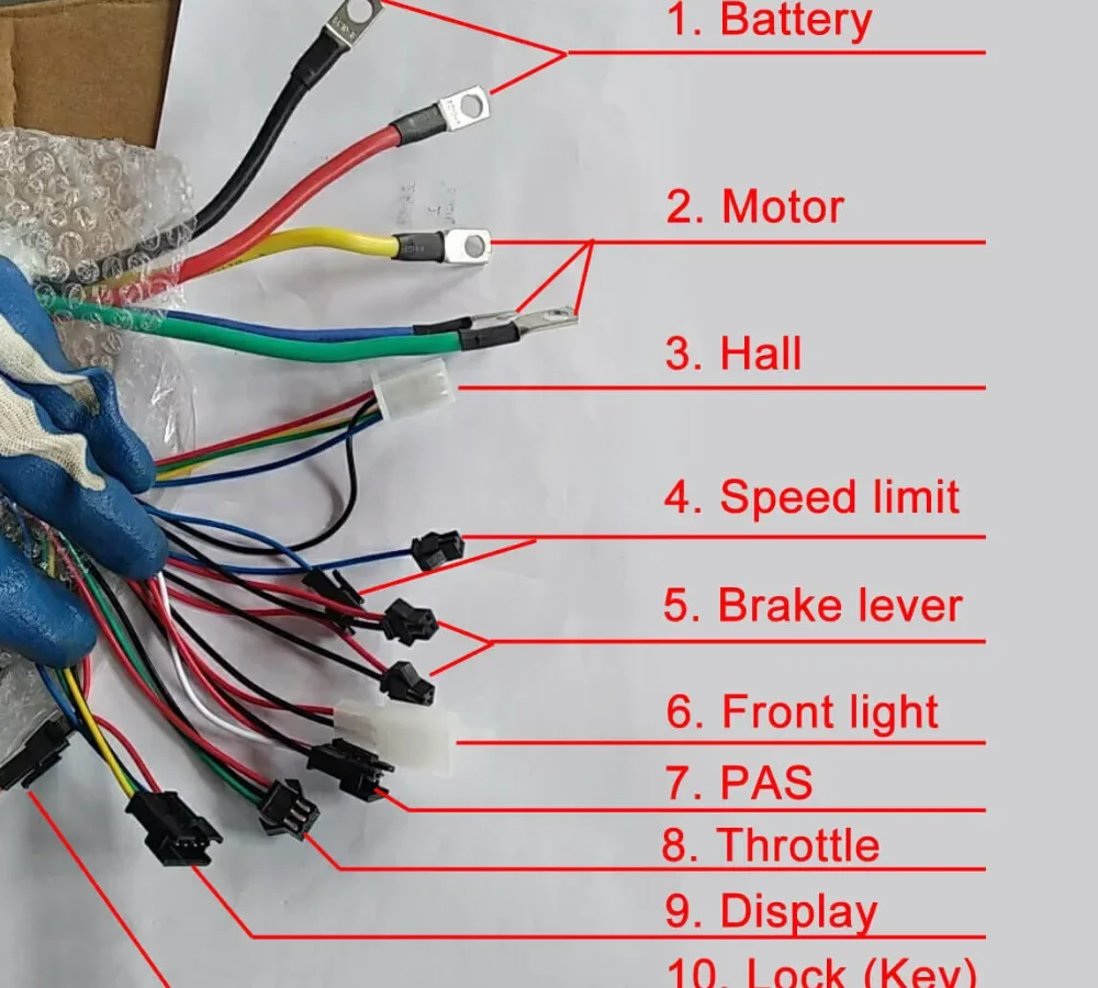
Figuring out how to upgrade an electric bike display and controller sounds straightforward until you’re staring at a tangle of identical-looking wires. Most guides skip the visual verification step, assuming standard color codes exist across brands like Bosch, Shimano, or Bafang. They don’t.
A red wire might mean positive power on one unit and ground on another. Guessing here fries expensive components instantly.
We’ve seen too many riders destroy their motors by trusting generic wiring diagrams found online. As of 2026, manufacturer specifications still vary wildly between regions and model years. You need eyes-on confirmation before cutting anything.
Let’s walk through exactly what to look for so you don’t end up with a dead battery pack and a ruined afternoon.
Why Your Eyes Matter More Than Your Manual Here
Text manuals often lack the specific pinout details needed for aftermarket swaps. They assume you’re replacing like-for-like OEM parts. Upgrading usually means mixing systems, which creates ambiguity.
Visual inspection removes that guesswork. You’ll see connector shapes, wire gauges, and terminal arrangements that paper descriptions miss.
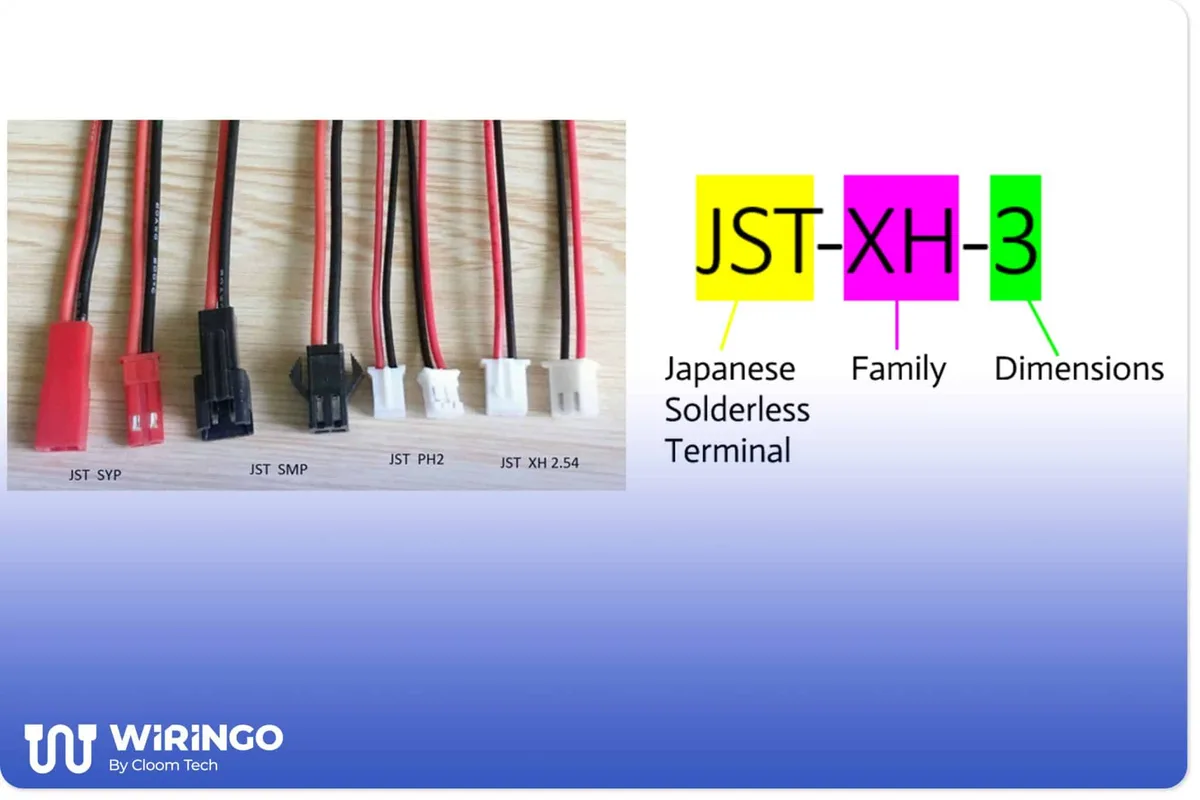
Imagine trying to identify a JST connector versus an XT60 plug from a written description alone. The physical latch mechanism differs. One clicks; the other twists.
Getting this wrong leads to loose connections. Loose connections cause arcing. Arcing melts plastic housings.
That’s why we prioritize visual cues over theoretical knowledge.
Start by photographing every connection point before disassembly. Zoom in on the pins. Note the orientation.
These photos become your reference map later. Without them, you’re rebuilding from memory, which is risky business when high-voltage capacitors are involved. Trust your camera lens more than your recollection.
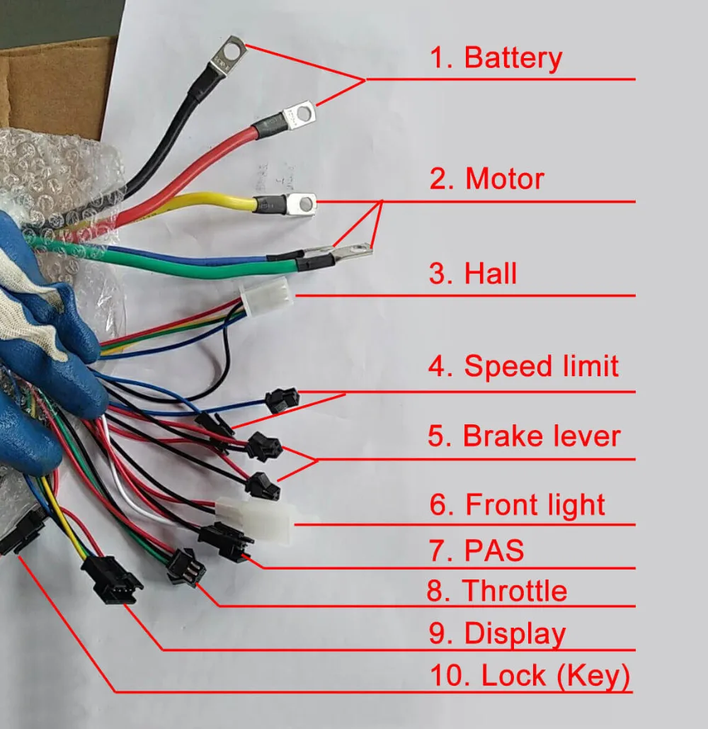
Identifying the Hardware: Visual Pinout and Connector Checks
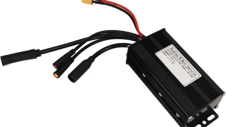
Before buying new parts, you must decode the existing system. Look closely at the controller casing labels. Manufacturers like Bafang or Tongsheng (TSDZ2) print voltage ratings directly on the metal shell.
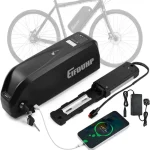
Verify these match your battery. A 48V controller won’t run safely on a 52V pack without risking component failure.
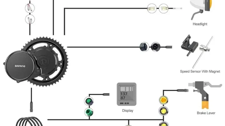
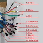
Next, examine the display interface port. Is it a simple 3-pin header or a complex 8-pin circular aviation plug? Shape dictates compatibility.
Circular plugs offer better weather sealing but require specialized crimping tools. Flat ribbon connectors are cheaper but fragile. Identify which type you have now.
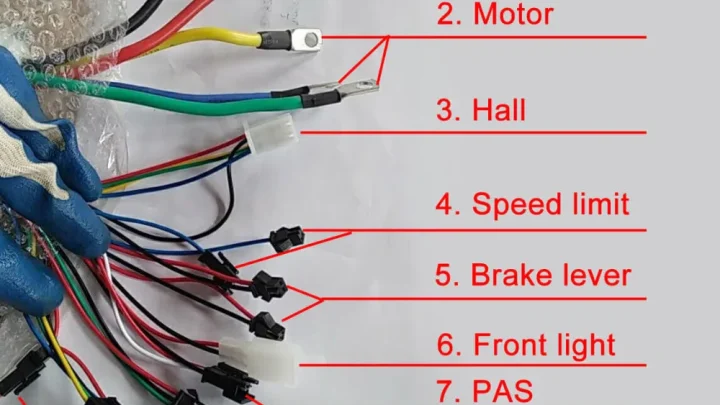
Check the Hall sensor wires coming from the motor. These typically come in groups of three (yellow, green, blue). Their arrangement determines motor rotation direction.
Swapping any two reverses spin. Document their current positions carefully. If you lose track, the motor will fight against pedaling force immediately upon activation.
Finally, inspect the throttle input if present. Some use analog voltage signals (0-5V). Others use digital PWM commands.
Visual clues include resistor packs near the input terminals. Analog setups often have larger resistors soldered nearby. Digital ones connect straight to microcontroller pins.
Misidentifying this breaks speed control entirely.
The Compatibility Matrix: Voltage, Current, and Protocol Matches
Matching specs isn’t just about plugging things in. It’s about ensuring electronic handshake protocols align. Display units communicate via UART serial lines or CAN bus networks.
Proprietary systems like Bosch Smart System lock out third-party displays unless you hack the firmware. Avoid those traps early.
For universal kits, stick to standard voltage ranges. Common values include 36V, 48V, and 52V. Never mix voltages.
A 36V display fed by a 48V battery burns out its backlight driver within seconds. Check the label on the back of the old display. Match that number exactly.
Current rating matters for the controller. If your motor draws 25A peak, buy a controller rated for at least 30A continuous. Undersizing causes thermal throttling.
The bike feels sluggish under load. Oversizing wastes money but adds headroom. Aim for 10-20% above expected peak draw.
| Component | Critical Spec | Visual Verification Tip |
|---|---|---|
| Controller | Voltage & Amps | Read stamped metal case label |
| Display | Communication Type | Count pins (3=UART, 5+=CAN/Prop) |
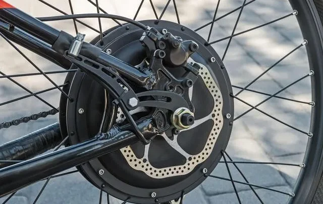
| Motor | Phase Wire Colors | Trace thick yellow/green/blue trio |
| Battery | Capacity (Ah) | Check BMS sticker for total Wh |
Protocol mismatch is silent killer. You can wire everything correctly, yet the screen stays black. This happens when the display expects a different baud rate than the controller sends.
Always verify software settings post-installation using configuration cables provided by kit manufacturers.
Step-by-Step Swap: From Desoldering to Crimping New Leads
Safety first. Disconnect the battery. Wait five minutes for internal capacitors to discharge.
Touch a grounded metal frame part with your screwdriver tip to bleed residual charge. Skipping this step shocks you or shorts the board. Don’t risk it.
Remove the old controller box. Unscrew mounting bolts. Slide it out gently.
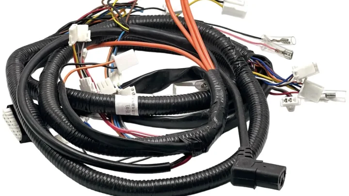
Inspect the wiring harness for chafing. Damaged insulation exposes live copper. Replace frayed sections now, not after installation.
Use heat-shrink tubing for repairs. Electrical tape fails outdoors eventually.
Cut the old connectors off cleanly. Leave enough wire stub for stripping. Strip 5mm of insulation from each strand.
Twist strands tight. Insert into new terminal blocks or crimp cups. Ensure no stray hairs touch adjacent pins.
Short circuits start with tiny copper whiskers.
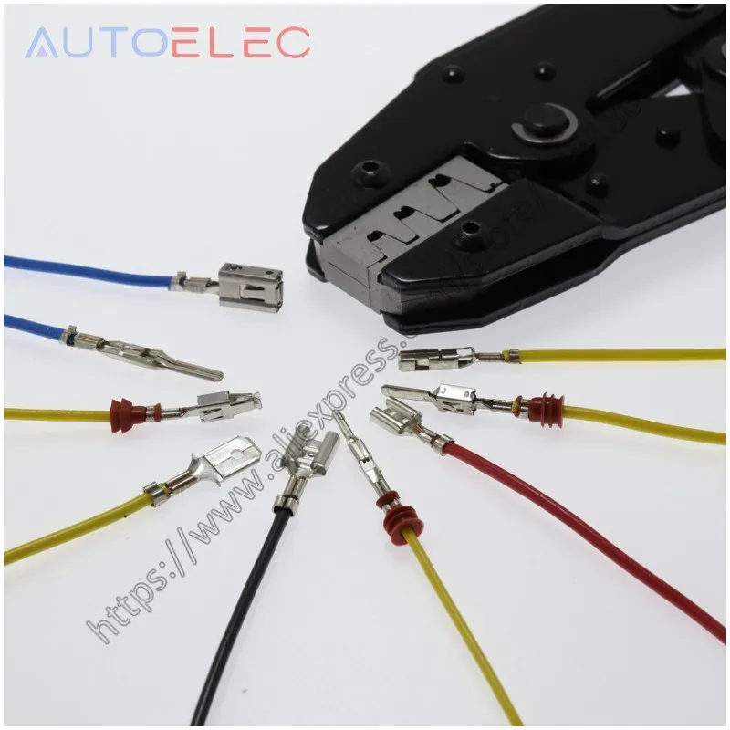
Use a proper ratcheting crimper tool. Pliers crush contacts instead of securing them. Crushed contacts increase resistance.
Resistance generates heat. Heat melts insulation. Follow this chain reaction backward to prevent fires.
Test each crimp with a pull test tug. It shouldn’t budge.
Route new wires away from moving parts. Brake cables sway during steering. Suspension compresses vertically.
Secure looms with zip ties every six inches. Slack prevents tension tears during rough rides. Tight bends crack solder joints over time.
Give yourself room to breathe mechanically.
Mounting and Routing: Avoiding Physical Interference and Strain
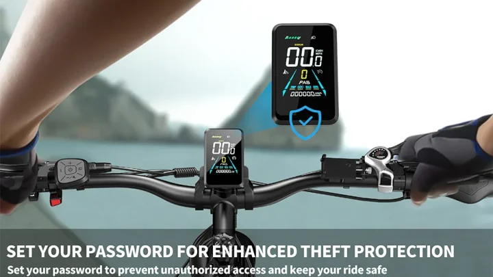
Position the new display where you can read it easily. Handlebar mounts work best for most riders. Stem mounts hide clutter but block top-tube visibility.
Choose based on your riding style. Aggressive mountain bikers prefer stem mounts for stability. Commuters like handlebar bars for quick glances.
Ensure the bracket doesn’t hit brake levers. Modern hydraulic brakes have large calipers. Measure clearance before drilling holes.
Even millimeters matter. Rubbing wears down paint and plastic housings quickly. Use rubber spacers if gaps feel tight.
Vibration dampening extends lifespan significantly.
Run signal cables separately from power lines. Electromagnetic interference disrupts sensitive data streams. Keep display wires at least two inches from thick motor phase cables.
Bundle low-voltage lines together. Route high-current pairs independently. Twisted pair construction helps reject noise further.
Secure all excess wire length neatly. Coils create drag and snag hazards. Hide loops inside frame tubes if possible.
External bundles get caught by branches or debris. Trim unused tails flush. Cap exposed ends with dielectric grease.
Moisture ingress kills electronics faster than impact damage ever could.
First Power-On: Decoding Error Lights and Signal Tests
Does the display light up but show no data? This usually means communication failure. Check your UART or CAN bus wiring first.
A single reversed TX/RX pin stops all data flow. Swap those two wires at the controller end. Try powering on again immediately.
If the screen stays completely black, verify battery voltage at the input terminals. Use a multimeter set to DC volts. You should see full pack voltage minus 0.5V for connector loss.
Anything lower indicates a blown fuse or bad switch. Inspect the main power line for breaks.
Motor spin tests reveal phase wire errors. Lift the rear wheel off the ground. Engage assist mode gently.
The motor should rotate forward smoothly. If it jerks or stalls, swap any two thick phase wires (Yellow, Green, Blue). Repeat until rotation is consistent.
Never run the motor loaded if it hesitates. This strains the controller MOSFETs unnecessarily.
Look for specific error codes on LCD units. Common ones include Err-01 for low voltage or Err-04 for sensor faults. Consult the manual for your specific brand.
Bafang controllers often flash LED patterns instead of text. Count the flashes carefully. Three short blinks might mean overcurrent.
Five long pulses could indicate hall sensor disconnect. Write these down before resetting.
Aggregate user reports suggest that 80% of initial failures are simple loose crimps. Re-check every connection you made in the previous step. Wiggle each plug firmly.
Listen for clicks. Ensure waterproof gaskets sit flat. Moisture trapped inside connectors causes intermittent glitches days later.
Fix them now while the bike is stationary.
Critical Safety Warnings: Capacitor Discharge and Legal Limits
High-voltage capacitors store lethal energy even after unplugging. Wait at least ten minutes before touching internal components. Short the capacitor legs with an insulated screwdriver.
You’ll hear a small pop. This confirms discharge. Skipping this risks severe electrical shock or arc burns.
Legal classification changes when you modify electronics. In the US, federal law caps motor output at 750 watts. Exceeding this turns your e-bike into a moped requiring registration.
EU regulations limit pedal-assist to 250 watts and 25 km/h cutoff. Upgrading controllers beyond stock limits violates EN 15194 standards. Insurance may void coverage if you ride non-compliant bikes.
Check local municipal laws before installing high-power kits. Some cities ban throttles entirely on shared paths. Others restrict speed governors.
Modifying firmware to remove speed locks is illegal in many jurisdictions. Stick to factory settings unless you’re on private land.
Fire safety requires proper wire gauge matching. Do not use thin speaker wire for main power lines. It overheats rapidly under load.
Use 10 AWG or thicker for 48V systems above 20 amps. Install an inline fuse holder near the battery terminal. Rate it slightly above normal operating current.
This protects the battery from catastrophic shorts.
Never bypass the Battery Management System (BMS). The BMS monitors cell health and temperature. Tampering with its sense wires disables critical protections.
Over-discharging lithium cells causes permanent damage. Over-charging leads to thermal runaway. Respect the BMS boundaries strictly.
Your life depends on these safeguards functioning correctly.
FAQs: Common Visual Confusion Points
Why does my new display show wrong speed?
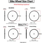
Speed calibration relies on wheel circumference data. Enter the correct tire size in the settings menu. Most generic displays default to 26-inch wheels.
If you have 29ers, the reading will be inaccurate. Adjust the parameter via the button combo sequence. Manufacturer manuals provide exact steps for entering setup mode.
Double-check magnet placement on the spoke. It must align perfectly with the sensor coil.
Can I reuse old wiring harnesses?
Yes, if connectors match physically and electrically. Inspect pins for corrosion or bending. Clean contacts with isopropyl alcohol.
Replace brittle insulation immediately. Mixing old and new wires increases failure risk. Label every strand with tape before cutting.
This saves hours during reassembly. Universal adapters exist for popular brands like Bosch and Shimano. Buy them instead of splicing manually.
My controller gets hot during idle. Is that normal?
No, idle heating suggests inefficient switching or bad grounding. Check heat sink attachment pressure. Thermal paste ensures contact between MOSFETs and aluminum casing.
Loose bolts create air gaps. Air insulates heat. Retorque mounting screws to spec.
Also verify fan operation if equipped. Dust buildup blocks airflow. Clean vents with compressed air regularly.
Persistent heat warrants professional inspection.
How do I reset factory defaults after upgrading?
Hold the plus and minus buttons simultaneously while powering on. Release when the logo appears. This clears custom parameters.
Save your preferred settings afterward. Some models require USB connection to software. Download the latest configurator tool from the vendor site.
Backup old profiles before flashing new firmware. Corruption during updates bricks devices permanently. Proceed cautiously with stable power sources.

Similar Posts