How to Find the Right E-Bike Controller Replacement
Founder & Technical E-Mobility Editor at Modern Electric Bikes · Professional Bicycle Mechanics Association (PBMA) Certified, Bosch & Shimano eBike Systems Certified · 14+ years in bicycle fabrication, electric hub & mid-drive motor diagnostics, and commuter road testing
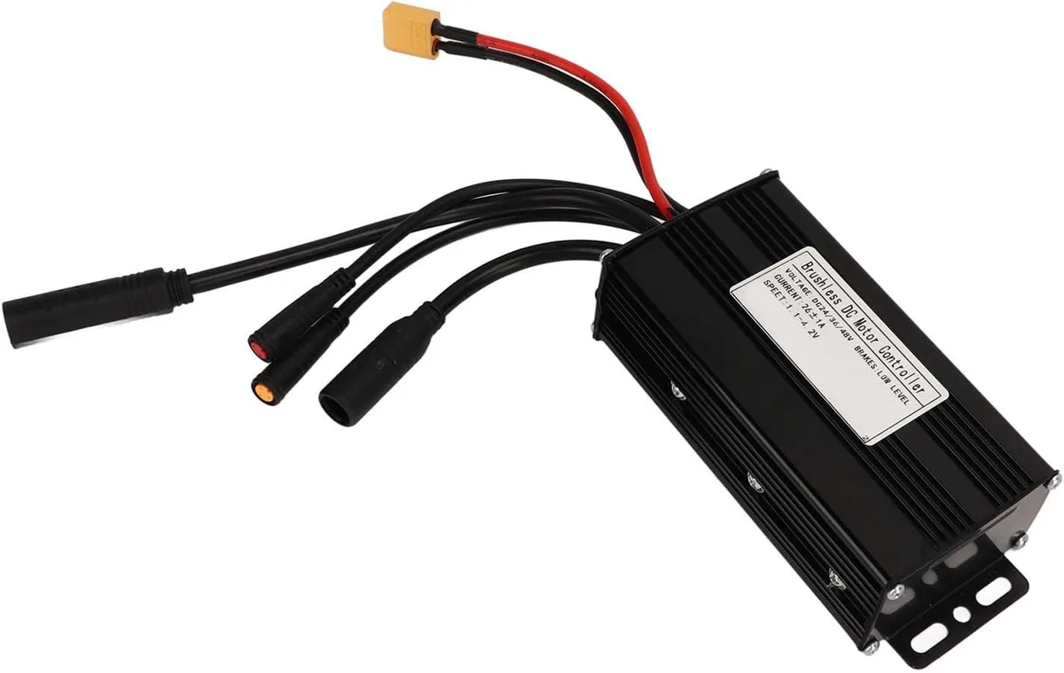
Figuring out how to identify the correct replacement electric bike controller starts with realizing that wattage alone is useless. You need to match voltage, amperage, sensor type, and physical connector layouts exactly. A mismatch can fry your new unit or damage the motor windings instantly.
We’ve seen too many riders assume a "48V 500W" label guarantees compatibility. It doesn’t. As of 2026, most modern hubs use sine-wave logic, while older kits rely on trapezoidal square waves.
Getting this wrong means jittery acceleration or total failure. Let’s walk through the diagnostic steps so you buy the right part the first time.
Quick Answer
To identify the correct replacement electric bike controller, check three specific specs on your old unit. First, verify the nominal battery voltage matches exactly. Second, ensure the continuous current rating equals or exceeds the original amp draw.
Third, confirm the sensor type aligns with your motor's Hall effect configuration. Finally, map every wire connector pinout before purchasing. Never guess based on wattage labels alone.
Physical fit and communication protocols matter just as much. Mismatches cause immediate hardware failure. Always disconnect the battery before inspecting wires.
Use a multimeter for continuity testing. This prevents short circuits during installation. Precision saves money and time.
Follow these steps strictly. Your e-bike will run smoothly again. Safety comes first in electrical work.
Take your time with diagnostics. Rushing leads to expensive mistakes. Document everything before removal.
Reference manufacturer datasheets when possible. Trust specs over marketing claims. Verify compatibility at every stage.
Double-check polarity connections twice. Test under load carefully. Avoid high-power bursts initially.
Monitor temperatures closely after startup. Ensure proper heat dissipation occurs. Secure all mounting brackets firmly.
Insulate exposed terminals properly. Respect local safety regulations always.
Image source: Web (Bing) / manuals.plus (Web image (fair-use with source credit))
Why Same Wattage Isn't Enough for Controller Replacement
Most riders think matching the "500W" sticker solves the problem. It doesn’t. Watts are a derived number, calculated by multiplying voltage and current.
Two controllers can both say 500W but behave completely differently. One might pull 10A at 50V. Another might pull 20A at 25V.
These aren’t interchangeable.
The real danger lies in the control algorithm. Older budget kits used square-wave switching. This creates torque ripple and audible noise.
Modern mid-range and premium bikes use Field Oriented Control (FOC). FOC produces smooth, silent power delivery. Plugging a square-wave controller into an FOC-ready motor causes inefficiency.
The motor may overheat due to harmonic distortion. Conversely, an FOC controller won’t recognize a basic square-wave motor without manual tuning. You’ll face cogging issues where the bike jerks forward unpredictably.
Physical constraints also play a huge role. Controllers vary wildly in size. A compact 36V unit won’t fit in a housing designed for a bulky 48V model.
Mounting holes rarely align across brands. You might drill new holes, compromising structural integrity. Water resistance ratings differ too.
An IP65-rated unit handles rain splashes. An IP54 unit fails quickly in heavy downpours. Replacing a sealed OEM unit with a generic open-frame board invites corrosion.
Moisture kills MOSFETs faster than overload does.
Finally, consider the communication layer. Many displays talk to the controller via proprietary serial protocols. Generic universal controllers often lack this handshake capability.
Your LCD might show error codes or stay blank. Throttle response becomes delayed or nonexistent. Brake cut-offs fail silently.
This isn’t just inconvenient. It’s unsafe if the brakes don’t kill power immediately. We prioritize exact spec matching over approximate wattage equivalence.
The label is a suggestion. The internal circuitry is the reality. Ignore it at your peril.
The Three Critical Variables That Determine Compatibility
Voltage is the non-negotiable baseline. If your battery pack is 48V nominal, the controller must accept that range. Most 48V systems operate between 42V (empty) and 54.6V (full charge).
A 36V controller will shut down or burn out at 48V input. Check the capacitor voltage ratings inside the old unit if the label is missing. Look for markings like "80V" or "100V" on large electrolytic capacitors.
This indicates the max safe input. Match this to your battery’s peak voltage. Never exceed the capacitor rating.
Current handling defines performance headroom. Continuous Amperage matters more than peak burst. A 15A continuous rating suits light commuting.
Cargo bikes need 25A to 30A minimum. Undersizing the current rating causes thermal shutdown. The controller gets hot and cuts power mid-hill.
Oversizing wastes money but adds safety margin. However, massive amps require thicker wiring. Your existing harness might melt if you push 40A through 14-gauge wires.
Assess your entire system capacity. Don’t upgrade the brain without checking the nerves.
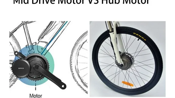
Sensor type dictates motor compatibility. Hub motors typically use Hall effect sensors. These provide rotor position data to the controller.
Some advanced setups use encoder-based feedback. Standard controllers expect six-step Hall signals. Sine-wave controllers interpret these signals to generate smooth magnetic fields.
Square-wave controllers chop the signal abruptly. Using the wrong type results in poor efficiency. Listen for whining noises from the motor.
Feel for vibration in the handlebars. These are signs of mismatch. Confirm whether your motor is brushed or brushless.
Nearly all modern e-bikes are brushless DC (BLDC). Brushed systems are obsolete. Focus on BLDC specifications exclusively.
| Variable | What to Check | Risk of Mismatch |
|---|---|---|
| Voltage | Nominal & Peak Input Range | Component Destruction / Fire Hazard |
| Current | Continuous Amp Rating | Thermal Shutdown / Wire Melting |
| Sensor Type | Hall vs. Encoder / Sine vs. Square | Motor Noise / Inefficiency / Jerkiness |
Step-by-Step: Diagnosing Your Old Controller’s Specs
Start by disconnecting the battery. Remove the fuse or unplug the main lead. Wait five minutes for capacitors to discharge.
Touch the battery terminals with an insulated screwdriver shaft to ground them. This prevents accidental shocks. Now locate the controller box.
It’s usually under the seat, near the bottom bracket, or inside the frame triangle. Unscrew the casing carefully. Note the orientation of screws for reassembly.
Read the primary label first. Manufacturers print voltage, amperage, and model numbers here. Photograph this label clearly.
If faded, look for internal component markings. Identify the main MOSFETs. Their part numbers reveal current capabilities.
Search online databases for these datasheets. They specify maximum drain-source current ($I_{DS}$). Multiply this by the number of parallel MOSFETs.
Divide by two for realistic continuous throughput. This gives you the true amp rating. Labels often exaggerate peak figures.
Internal silicon tells the truth.
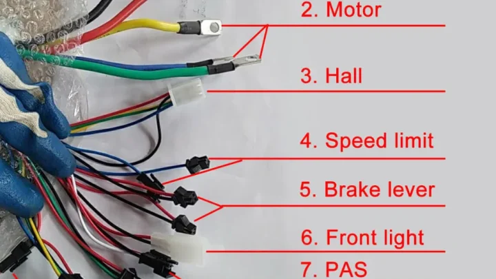
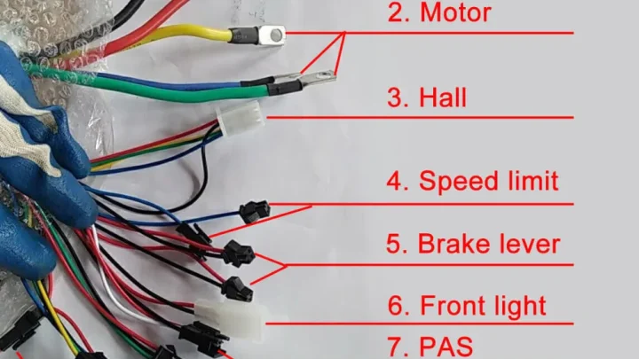
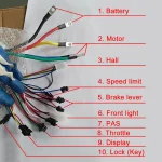
Next, trace the wire bundles. Separate them by function. Battery leads are thick and red/black.
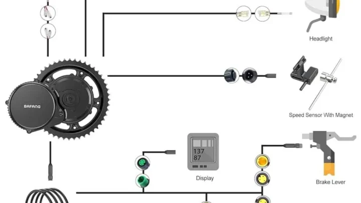
Motor phase wires (U, V, W) are usually yellow, green, blue. Hall sensor wires are thinner, often five strands including 5V and Ground. Throttle inputs have three wires: Signal, 5V, Ground.
Brake levers connect via two-wire loops. Display cables vary widely. RJ45 ports are common for smart displays.
JST connectors suit simpler units. Label each bundle with masking tape. Write its destination.
This map is crucial for the swap. Without it, you’re guessing polarity. Guessing kills electronics.
Use a multimeter set to continuity mode. Probe the Hall sensor pins against the 5V rail. You should see low resistance.
High resistance implies broken sensors. Test the throttle signal wire. Rotate the grip slowly.
Voltage should rise linearly from 0.8V to 4.2V. Flat spots mean a worn potentiometer. Replace the throttle if needed.
Check brake switches. They should read open circuit when released. Close circuit when engaged.
Faulty brakes prevent power cutoff. Fix these before installing the new controller. Garbage in, garbage out.
Clean inputs ensure clean operation.
Matching Connectors, Sensors, and Communication Protocols
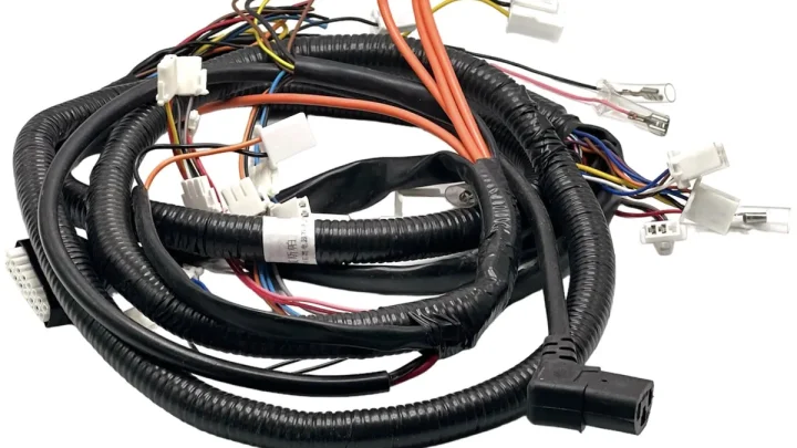
Connector types are the biggest headache in replacements. OEM manufacturers use proprietary plugs to lock users in. Aftermarket controllers come with loose pigtail wires.
You cannot simply plug one into the other. You must adapt. Cut the old connectors off.
Strip the insulation back 10mm. Tin the copper strands with solder. This prevents fraying.
Match wire colors logically. Red to positive. Black to negative.
Blue/Green/Yellow to phases. White/Gray/Purple to Halls. Do not trust color codes blindly.
Verify with a multimeter. Colors change between batches. Continuity tests do not lie.
Sensor alignment requires precision. Hall sensors sit 120 degrees apart electrically. Some motors use 60-degree spacing.
The controller must know which layout it faces. Most universal controllers auto-detect this. But some require jumper settings.
Locate the DIP switches or programming port. Set the angle correctly. Wrong angles cause reverse rotation or stalling.
Spin the wheel manually. Watch the display RPM. It should increase steadily.
Erratic jumps indicate misalignment. Adjust until smooth. This step takes patience.
Rushing ruins the calibration.
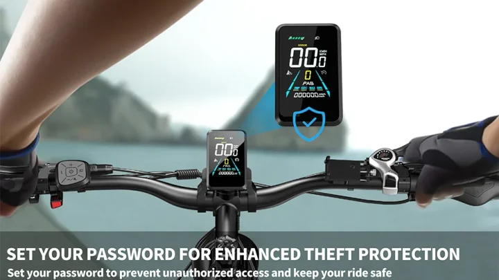
Communication protocols determine feature access. Basic controllers ignore data lines. Smart controllers read CAN bus or UART streams.
Your display sends speed, distance, and assist levels. The controller replies with status flags. If the protocol mismatches, the screen freezes.
Error code E01 often appears. This means no communication detected. Check the cable shield grounding.
Poor shielding introduces noise. Noise corrupts digital packets. Re-route signal wires away from power lines.
Keep them perpendicular if crossing is unavoidable. Twisted pair cables reduce interference significantly. Upgrade cheap ribbon wires if necessary.
Reliable data flow ensures responsive assistance. Without it, you lose pedal assist modes. You’re stuck in throttle-only mode.
That violates legal limits in many regions. Restore full functionality by fixing comms.
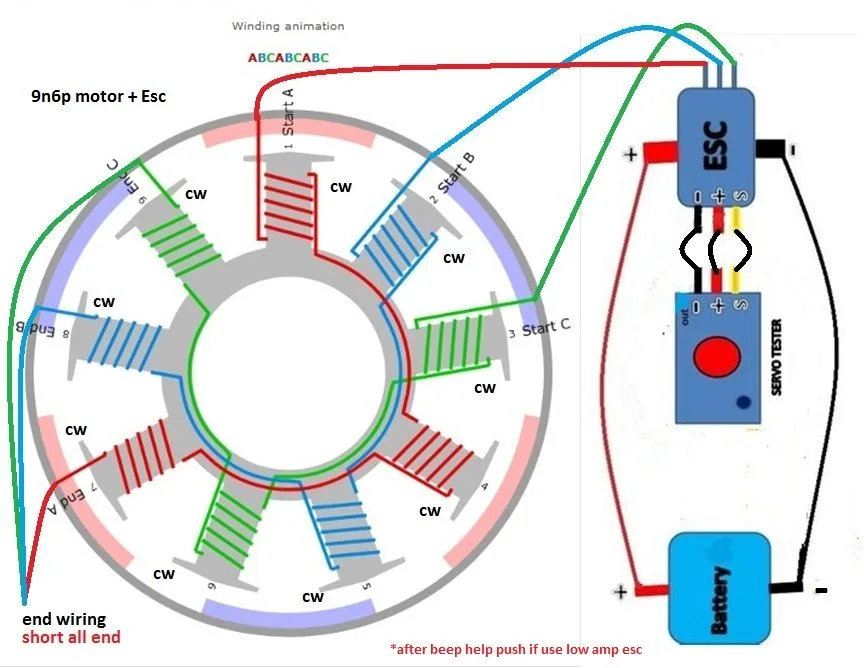
Image source: Bing (Web (fair-use with source credit))
Physical Fitment and Thermal Headroom Checks
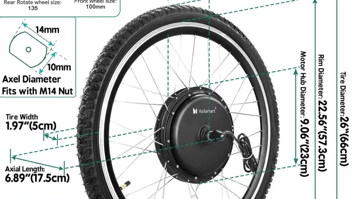
Measure the old controller’s dimensions precisely. Length, width, height, and mounting hole spacing. Compare these to the new unit’s specs.
If the new box is larger, it won’t close the cover. Forcing it cracks plastic housings. Cracks let water in.
Water shorts circuits. Choose a form factor that fits easily. Leave 5mm clearance on all sides.
Airflow needs space. Tight squeezes trap heat. Heat throttles performance.
The controller reduces power to protect itself. You lose speed on hills. Adequate ventilation maintains peak output.
Thermal management is critical for longevity. MOSFETs generate waste heat proportional to current squared. Doubling amps quadruples heat.
Check the heatsink design. Large aluminum fins dissipate energy better. Small plastic cases insulate dangerously.
Add thermal pads between chips and the case. These transfer heat efficiently. Dry paste works poorly.
Pads conform to uneven surfaces. Ensure tight bolt pressure. Loose contacts create air gaps.
Air is an insulator. Hotspots develop rapidly. Measure temperature after a test ride.
Use an infrared thermometer. Surface temps shouldn’t exceed 80°C. Internal junction temps reach 150°C safely.
Exceeding this triggers shutdown. Consistent overheating degrades components. Electrolytic capacitors bulge and leak.
Leaked fluid corrodes PCB traces. Corrosion breaks connections permanently. Prevent this with proper cooling.
Mounting brackets affect vibration resistance. E-bikes shake violently on rough roads. Bolts loosen over time.
Use thread-locker compound on screws. Blue Loctite suffices. Red requires heat to remove.
Apply sparingly. Excess glue jams threads. Secure the controller firmly.
Rubber grommets absorb shock. Metal-on-metal contact transfers fatigue. Fatigue cracks solder joints.
Cracked joints cause intermittent failures. Hard to diagnose. Easy to prevent.
Inspect mounting points regularly. Retorque after the first 50 miles. Settling occurs initially.
Stay vigilant early on. Long-term stability depends on initial care. Don’t skip these small steps.
They save big repairs later.
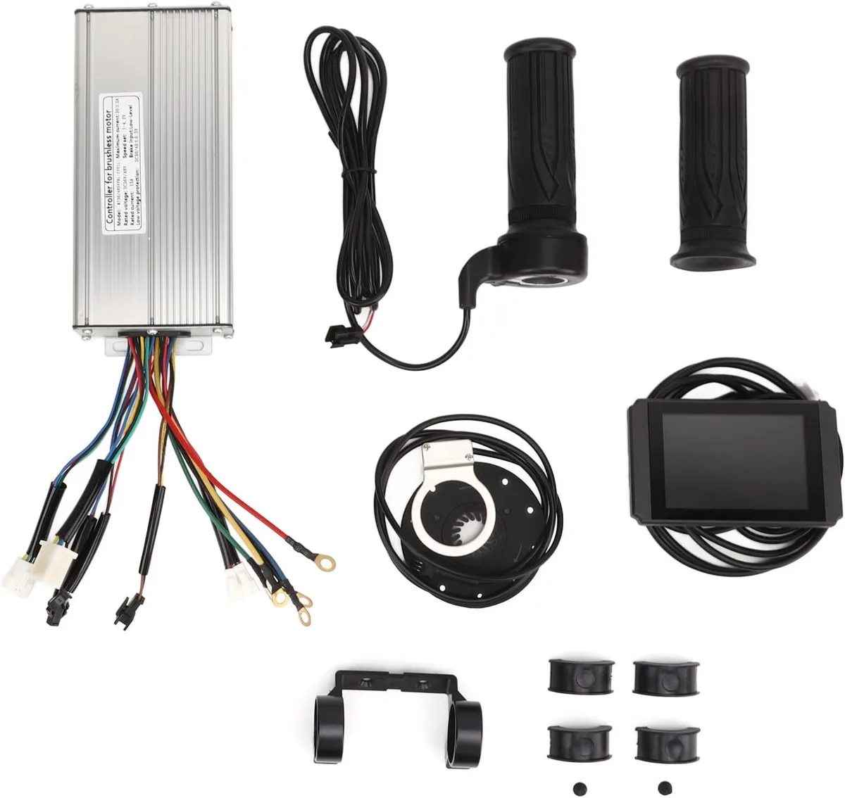
Image source: Web (Bing) / manuals.plus (Web image (fair-use with source credit))
Common Wiring Mistakes That Fry New Controllers
Swapping controllers isn’t just about plugging in wires. It’s about respecting the electrical logic behind them. The most fatal error is reversing polarity on the battery leads.
Connect red to negative, and you’ll blow the input capacitors instantly. This creates a short circuit that sparks and smokes. Always double-check markings before tightening terminals.
Use heat-shrink tubing on every exposed connection. Bare copper touching metal frames causes shorts. These shorts trip breakers or damage MOSFETs permanently.
Another frequent mistake involves mixing up motor phase wires. U, V, and W must match their counterparts exactly. Swap two phases, and the motor spins backward.
You might not notice until you try to ride. The bike lurches unexpectedly. This stresses the drivetrain and risks injury.
Verify rotation direction with the wheel off the ground first. If it spins wrong, swap any two phase wires. Never touch the Hall sensor wires during this test.
Those provide position data, not power. Confusing them confuses the controller’s timing.
Brake cut-off wiring often gets ignored too. Many riders bypass these switches for "convenience." This removes a critical safety layer. If the brakes fail mechanically, the throttle remains active.
That’s a recipe for disaster. Ensure the brake lever triggers a high or low signal correctly. Most systems use normally-open switches.
Closing the circuit cuts power. Test this with a multimeter before riding. Don’t assume the factory setting is right.
Modifications happen. Verify independently. Ignoring this step voids insurance coverage in many jurisdictions.
Safety interlocks exist for a reason. Respect them strictly.
Safety Precautions Before You Power On
Electricity doesn’t forgive mistakes. Lithium-ion batteries store immense energy. A single slip can cause thermal runaway.
Wear insulated gloves when handling main leads. Remove jewelry that could bridge terminals. Rings and watches conduct electricity efficiently.
They burn skin instantly upon contact. Keep a Class C fire extinguisher nearby. Standard water extinguishers worsen lithium fires.
Sand or specialized agents are safer bets. Work in a well-ventilated area. Fumes from burning insulation are toxic.
Avoid enclosed garages without fans.
Disconnect the charger completely before starting work. Residual voltage lurks in charging circuits. It surprises even experienced technicians.
Wait ten minutes after unplugging. Let internal capacitors drain fully. Measure voltage at the controller input pins.
It should read near zero. If it holds charge, discharge it safely. Use a resistor bulb load.
Never short terminals directly. That arc welds metal together. Precision matters more than speed here.
Rushing invites catastrophe. Patience prevents hospital visits. Treat every wire as live until proven dead.
Inspect the new controller for shipping damage. Cracked casings compromise waterproofing. Loose components indicate poor quality control.
Check solder joints under magnification. Cold solder looks dull and grainy. It fails under vibration.
Reflow weak joints if necessary. Ensure all screws are tight. Vibrations loosen fasteners over time.
Apply thread locker to mounting bolts. This secures the unit firmly. A loose controller rattles against the frame.
That noise distracts riders. More importantly, it damages connections. Secure everything before the first spin.
Test idle operation first. No load means no risk. Observe LED indicators closely.
Any flickering signals trouble. Stop immediately if anomalies appear. Diagnose before escalating power.
Frequently Asked Questions About E-Bike Controller Swaps
Can I use a higher amp controller?
Yes, provided your wiring supports it. Thicker gauges handle increased current safely. Check your battery’s max discharge rate.
Exceeding BMS limits trips protection modes. The system shuts down unexpectedly. Match controller amps to cable capacity. 10-gauge wire handles 30A comfortably. 12-gauge struggles past 20A continuously.
Upgrade harnesses alongside controllers. This ensures balanced performance. Don’t overload thin wires.
They melt internally. Visible damage appears late. Preventative upgrades save headaches later.
Do I need to program the new controller?
Often, yes. Universal units require setup menus. Set voltage cutoffs to protect cells.
Configure current limits for motor safety. Enable or disable regen braking features. Adjust acceleration curves for comfort.
Some models use Bluetooth apps. Others rely on display buttons. Read the manual thoroughly.
Default settings may not fit your bike. Incorrect parameters cause harsh behavior. Tuning optimizes efficiency and feel.
Spend time on configuration. It pays off in ride quality. Skip this step at your peril.
What if my display stops working?
Check the communication protocol first. Mismatched baud rates break data links. Verify pinout alignment on the connector.
One swapped wire kills the signal. Inspect the cable for breaks. Flex points wear out quickly.
Replace damaged sections entirely. Test with a known-good display. This isolates the fault source.
If the display works elsewhere, the controller is guilty. Contact the manufacturer for firmware updates. Sometimes bugs prevent initialization.
Resetting helps occasionally. Persistent issues imply hardware failure. Return defective units promptly.
Don’t struggle with broken tech. Support exists for a reason. Use it wisely.

Similar Posts